1. Introduction
The Checkmk hardware appliance differs from the virtual appliance in a number of points.
Firstly, the racks have a RAID 1 connection and a corresponding additional menu item in the web interface.
Secondly, a separate management interface is available via which the rack can be controlled independently of the regular network connection.
In addition, you can provide the racks with an SMS modem in order to be reliably notified in the event of failures.
We will explain all of these aspects in this article, everything else can be found in the main appliance article.
2. The RAID array
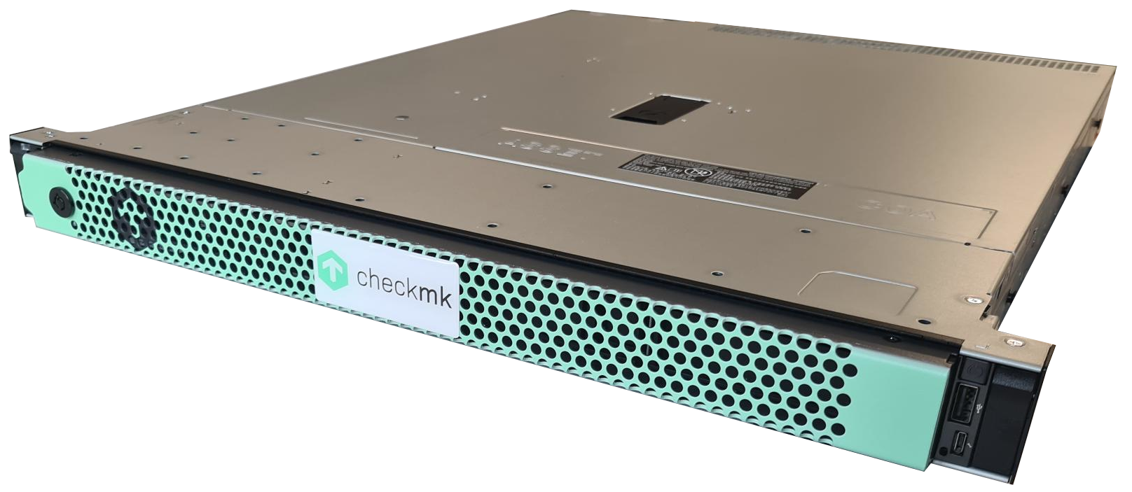
Your rack has two occupied hard drive bays at the front of the enclosure. These are marked with the numbers 0 and 1 on the rack4 devices. The hard drives installed here are connected together in a RAID 1 array (mirror) so that your data is stored redundantly on both hard drives. Should one of the hard drives fail, the data will still be available on the second hard drive.
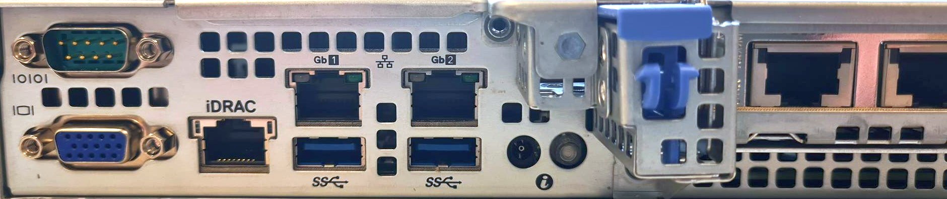
3. Ports of the rack
The rack is designed for redundancy and remote maintenance — so use both power supplies! And the management interface, to absolutely not need physical access in the future.

The racks also feature an extension with two additional network ports - for further redundancy in cluster operation.
If you are using a rack4+: For the initial setup, you must use one of the copper network ports. You cannot initially obtain an IP address via the additional fiber interfaces; you can only do this via the web interface.
Management in the web interface
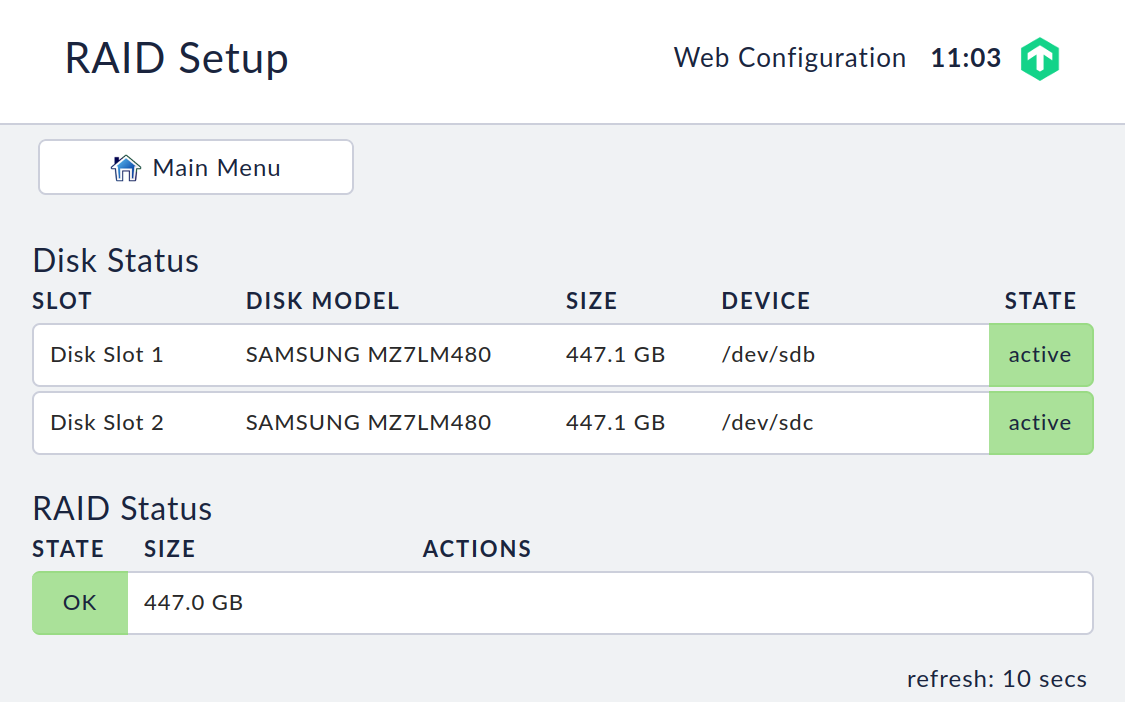
You can view the status of the RAID in your appliance’s web interface. To do this, select the RAID-Setup item in the web interface’s main menu. You can also carry out a repair of the RAID from this screen, should it be necessary.
Replacing a defective hard drive
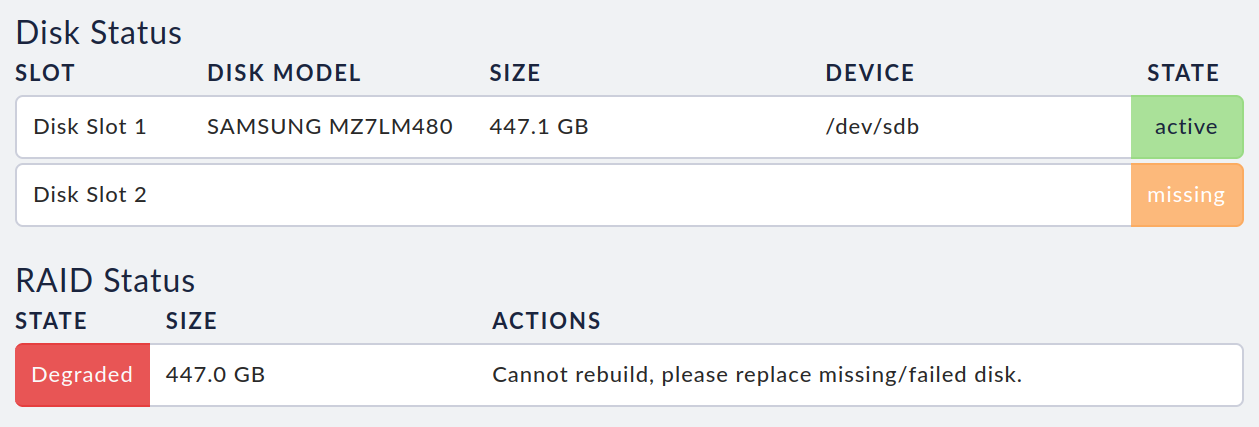
If a hard disk is detected as being defective, it is displayed in the web interface as Degraded. On the unit itself, depending on the type, the error will be indicated by a blue flashing LED lamp on the hard drive bay.
By pressing the small lever on the left side of the slide-in module, the assembly is unlocked and you can pull the tray including the hard drive out of the enclosure. Now you can loosen the screws on the bottom of the tray and remove the defective hard drive from the tray. Mount the new hard drive in the tray and push it back into the free slot in the device.
If the unit is switched on while you replace the hard disk, the RAID rebuild process will start automatically. You will be able to see the rebuild’s progress in the web interface.
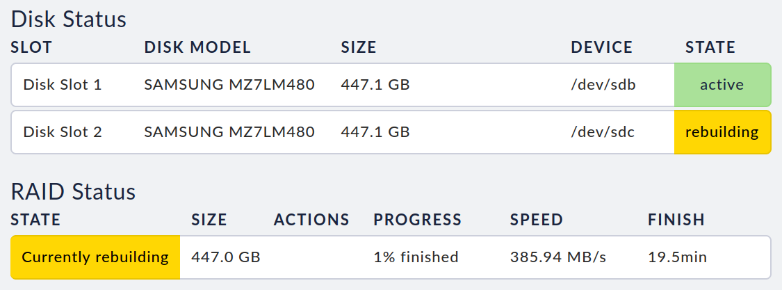
The fail-safe function will only be restored after the RAID has been completely repaired.
Defects in both hard drives
If the unit detects that both hard disks are defective or have been removed, a restart will be triggered automatically.
4. The rack’s management interface
Your rack has a built-in management interface (Dell iDrac). You can use this management interface’s web interface to, for example, control the unit if it is not switched on or is no longer accessible, and to remotely control the local console.
If you want to use the management interface, you must first connect the dedicated IPMI LAN port to your network.
Caution: For security reasons, we recommend connecting the IPMI-LAN to a dedicated management network, if possible.
The management interface is supplied in a deactivated state. You can activate and configure it via the Management Interface option in the device settings.
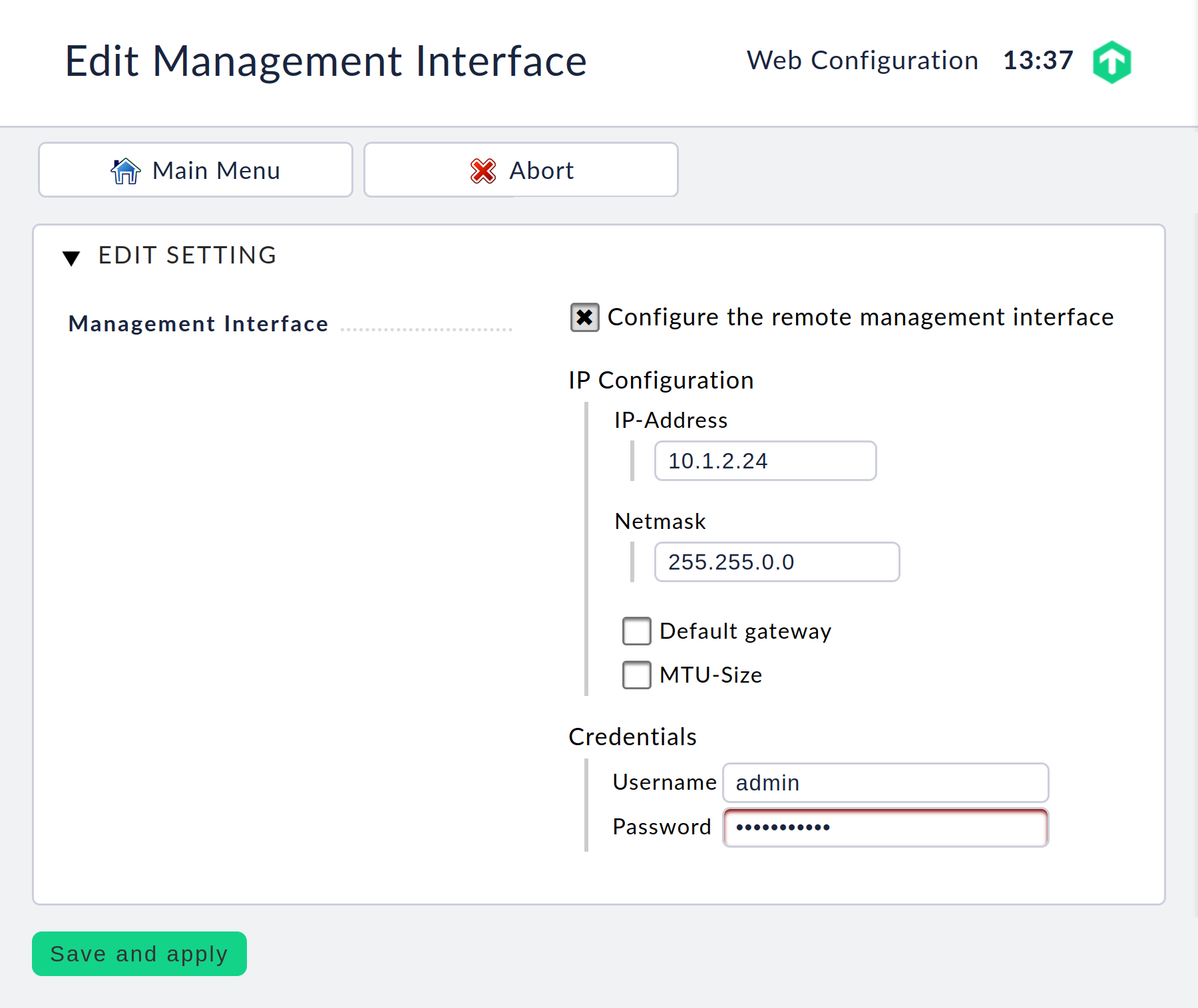
Here you must assign a separate IP address for the management interface and define dedicated access data for access.
After you have saved these settings, you can open the management interface’s IP address with your web browser and there log in with the access data you have just defined.
Important: The settings for the management interface are persistent, i.e. they are retained even when you reset to the factory settings. This ensures that you will no longer need physical access to the rack later.
5. SMS notifications
5.1. Hardware
It is possible to connect a GSM modem to the appliance in order to send SMS notifications, in the event of critical problems, for example.
It is currently not possible to purchase a UMTS/GSM modem together with the appliance or subsequently as an accessory. However, there are various modems, such as the MTD-H5-2.0, that are compatible with the appliance.
5.2. Putting the modem into operation
To put the modem into operation, you must insert a functioning SIM card and connect it to a free USB port on your appliance.
Once this is done, the appliance automatically detects the modem and sets it up. Open the appliance’s web interface and select the Manage SMS. module. This page shows you the current status of the modem and its connection to the mobile network.
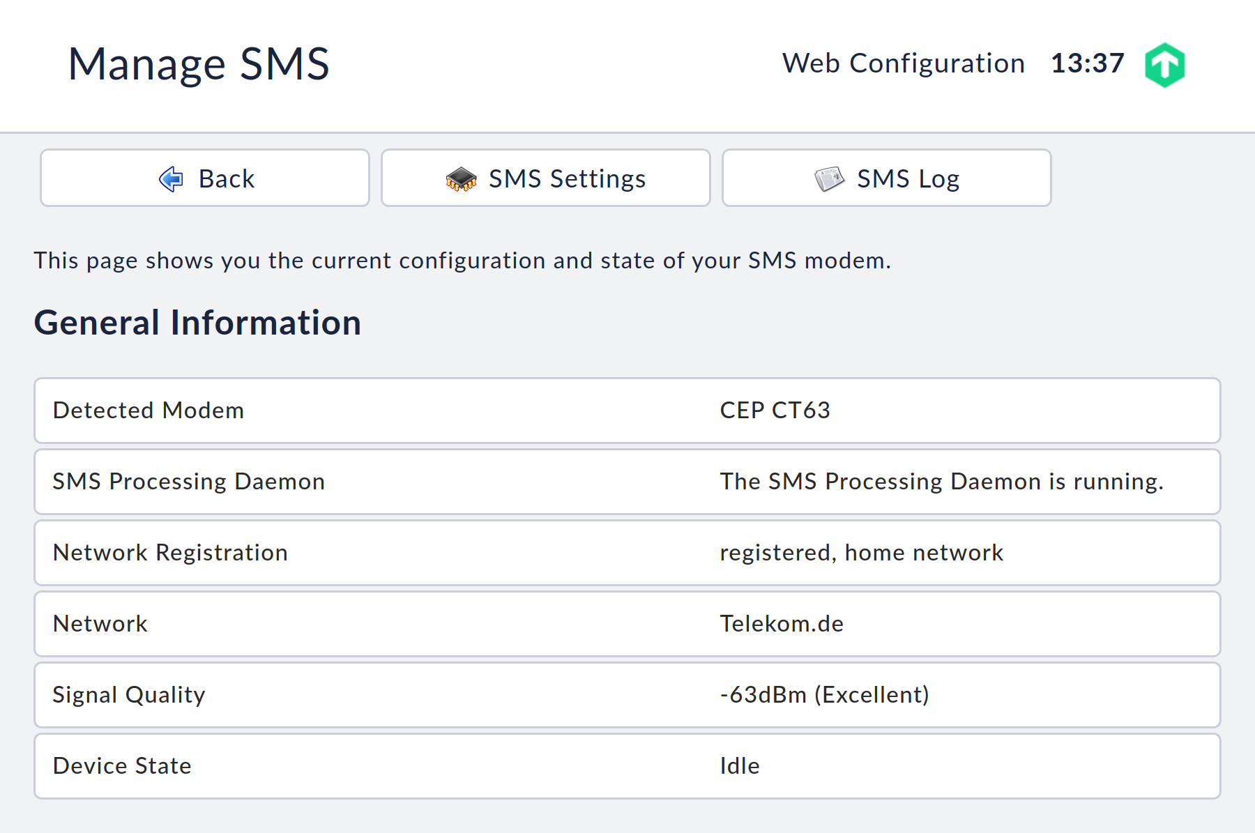
If you need to enter a PIN to use your SIM card, you can enter it under SMS Settings.

5.3. Troubleshooting
If sent messages do not reach you, you can view all sent, unsent and queued messages on the Manage SMS page. The entries in these lists are kept for a maximum of 30 days and then automatically deleted.
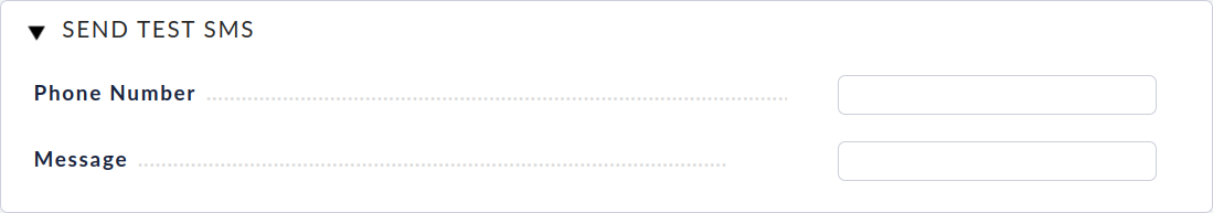
It is possible to send a test SMS to a number of your choice via the Send test SMS menu item.
The phone number must be entered without leading zeros and without a leading plus sign, e.g. 491512345678 for a mobile phone number in Germany.
Further information on possible errors when sending SMS messages can be found in the SMS Log.