1. The basics
You can connect two Checkmk appliances to form a failover cluster. In doing so, all configurations and data are synchronized between the two appliances. The appliances that are connected as a cluster are also referred to as nodes. One of the nodes in the cluster takes on the active role, i.e. performs the cluster’s tasks. Both nodes constantly exchange information on their status. As soon as the inactive node recognizes that the active node can no longer fulfill its tasks, due to a failure, for example, the inactive node takes over the active node’s tasks and then becomes the new active node.
The failover cluster is there to increase the availability of your monitoring installation by securing it against hardware failures in a device or individual components. However, clustering does not replace data backup and does not detect logical errors.
In the following situations, the cluster reduces downtime by allowing the inactive node to take over its resources:
When the RAID in a Checkmk rack is no longer accessible.
When the previously active device is no longer accessible (failed).
If the previously active device can no longer reach the 'external' network, but the inactive node can.
If you perform a firmware update on the nodes.
The cluster can of course only function in an emergency if the nodes are operated via separate switches and power supplies!
2. Prerequisites
In order to set up a cluster, you will first need two compatible Checkmk appliances. The following models can be combined into a cluster:
2 x Checkmk rack1
2 x Checkmk rack4
2 x Checkmk virt1 (technically possible, but not supported or recommended for production. See below for details.)
1 x Checkmk rack1/rack4 and 1 x Checkmk virt1
Furthermore, the two appliances must use a compatible firmware. If you combine a virt1 appliance with a physical rack, the virtual machine must have the same specifications as the physical server — otherwise it could crash when it takes over the load from the rack.
The units must be wired with at least two independent network connections. One of these connections is used for the normal network connection, the second for synchronization between the cluster nodes. The sync connection should run directly between the units where possible, but as a minimum via a separate network.
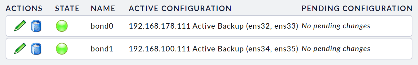
To increase the availability of the network connections, you should create a bonding configuration that uses all four network ports in the Checkmk racks instead of configuring only two individual ports.
In doing so, use the LAN1 and LAN2 ports to connect to your network and the LAN3 and LAN4 ports for the direct sync connection between the units.
Virtual machines: It is certainly technically possible to cluster two virt1 instances. However, since the cluster function is designed to compensate for hardware failures, we do not recommend this for production operation. For high availability, virtualization platforms such as VMware ESXi provide their own functions. However, you can very easily test the behavior and configuration of a cluster with two virtual machines. 'Desktop virtualizers' such as VirtualBox or VMware Workstation Player are also suitable for this. With these solutions you can dispense with the bonding configuration. Instead of setting up the bonding as shown below, simply use the unused second network interface. For the actual clustering, simply select your two individual interfaces instead of the bonding interfaces.
3. Configuring a cluster
These instructions assume that you have already preconfigured both devices to the point where you can open their web interfaces with a web browser.
Before actually setting up the cluster, you must first prepare both devices. In doing so, you mainly have to modify the network configuration so that the requirements mentioned above are fulfilled. Note the ports used for clustering, if necessary.
The following describes the configuration of a cluster with two bonding interfaces, which corresponds to the following diagram:
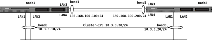
The interface designations LAN1, LAN2 etc. used in the diagram correspond to the designations of the physical interfaces on the device. In the operating system, LAN1 corresponds to the device eth0, LAN2 to the device eth1, etc.
The IP addresses used are of course arbitrary. However, make sure that the internal cluster network (bond1 in the diagram) uses a different IP network than the 'external' network (bond0 in the diagram).
Note: The following screenshots were created from a virt1 cluster — so the names of the network interfaces accordingly differ.
3.1. Network configuration
Open the first node’s web interface, select the device settings and at the top, the Network Settings. Two modes are available here.
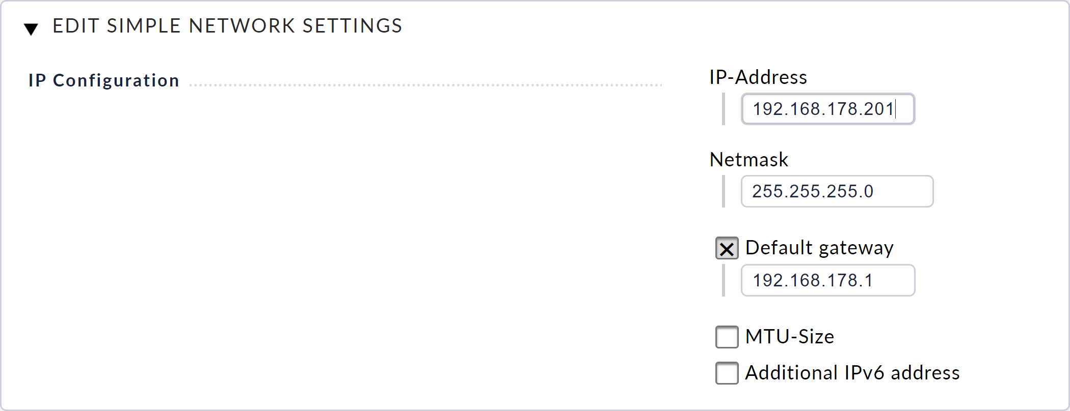
The Simple Mode, with which you can configure only your device’s LAN1, is activated by default. (This mode corresponds to the configuration via the text console that you performed during the initial setting up of the appliance).
The advanced mode is required for clustering. To activate this mode, click on the Advanced Mode button at the top and confirm the security prompt.
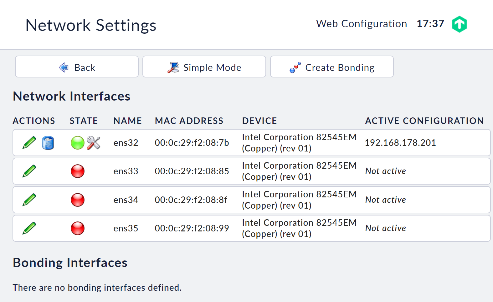
On the following page you will see all of the network interfaces available in the unit. Only the standard interface (on the racks eth0 via the socket LAN1), currently has a configuration — here ens32 in the below screenshot. This was taken over from the Simple mode.
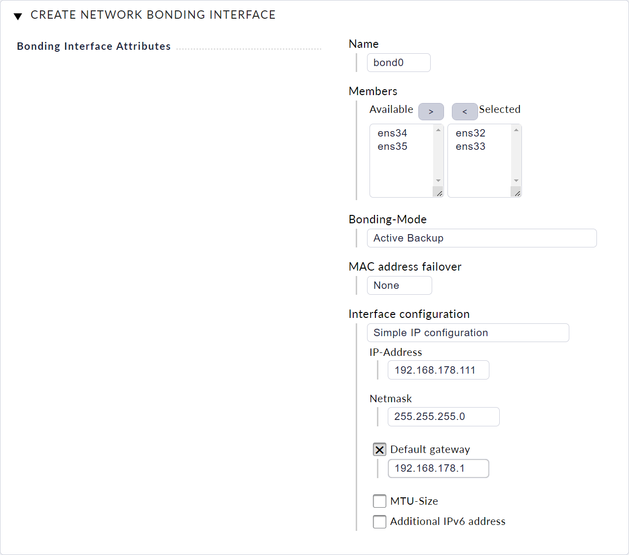
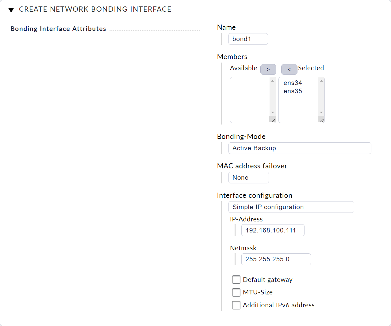
Now create the first bonding interface bond0 by clicking on Create Bonding. In the following dialog, enter all data as shown in the following screenshot and confirm the dialog with Save.
Next create the second bonding interface bond1 with the appropriate configuration for the direct sync connection.
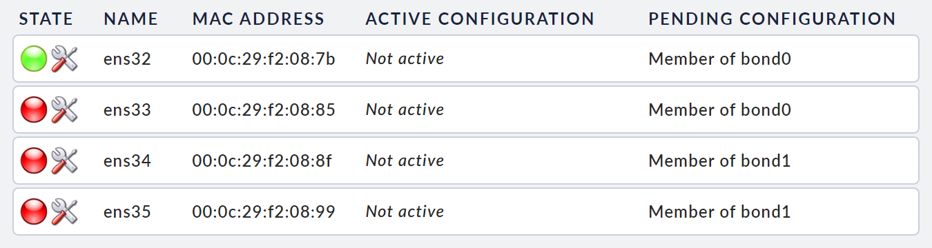
After you have created the two bonding interfaces, you will once again see all of the settings made in the network configuration dialog for the network interfaces …
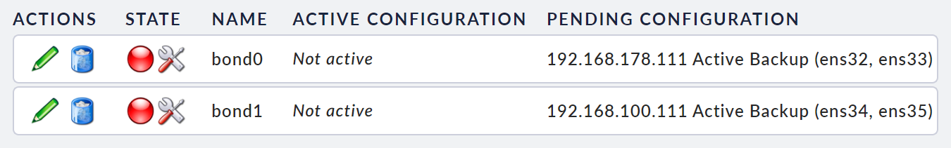
… and for the bondings that have been created:
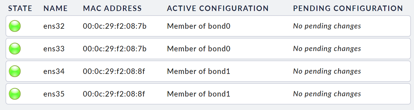
When you have successfully completed all of the configuration steps, click on Activate Changes to make the settings effective. The new network settings will then be loaded. After a few seconds the network configuration will show the status 'OK' everywhere, for the real network interfaces …
… and again at the bondings:
Now repeat the configuration of the network settings with the appropriate settings on your second device.
3.2. Host names
Devices that are to be connected in a cluster must have different host names.
You can now define these in the device settings.
In our example, the appliances have been given the names cma1 and cma2.
3.3. Connecting the cluster
Now that you have completed the preparations, you can continue with setting up the cluster.
To do this, open the Clustering module on the web interface in the main menu of the first device (here cma1) and there click on Create Cluster.
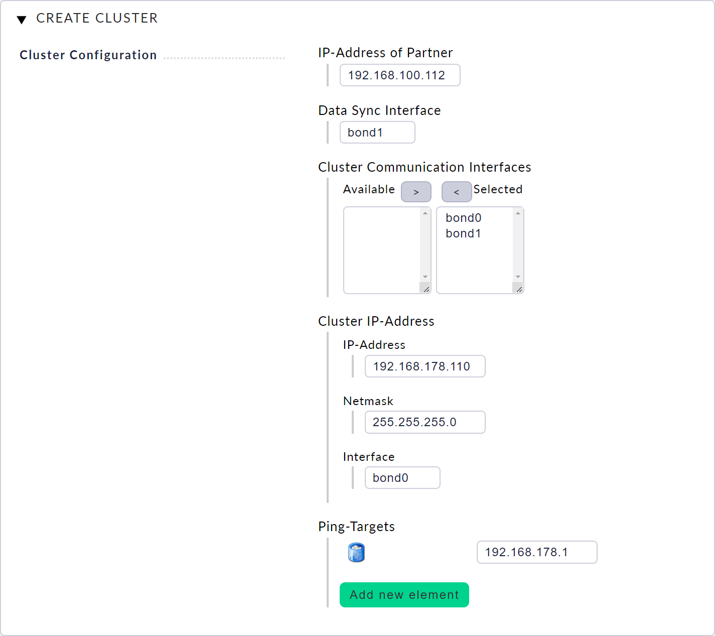
In the dialog for creating the cluster, enter the corresponding configuration and confirm the dialog with Save. The Cluster IP address, which you will use later to access the cluster, is particularly important here. If you need further information on this dialog, call up the inline help via the icon next to the Checkmk logo.
On the following page, you can connect the two devices to a cluster. To do this, you must enter the password for the second device’s web interface. This password is used once to establish the connection between the two units. Confirm the security prompt if you are sure that you want to overwrite the data on the displayed target device.

Once this connection has been successfully established, synchronization of the cluster’s devices will begin. You can view the current status of this process on the cluster page. During the synchronization, all resources, including any existing monitoring sites, will be started on the first node.
From now on, with the help of the cluster IP address (here 192.168.178.110), you will be able to access the cluster’s resources, e.g. your monitoring sites — regardless of which node is currently holding the resources.
4. Status of the cluster
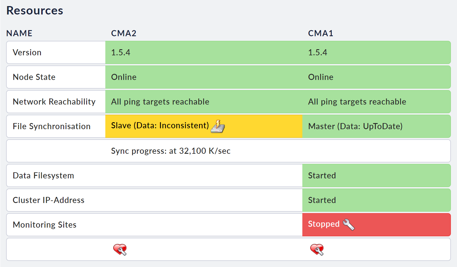
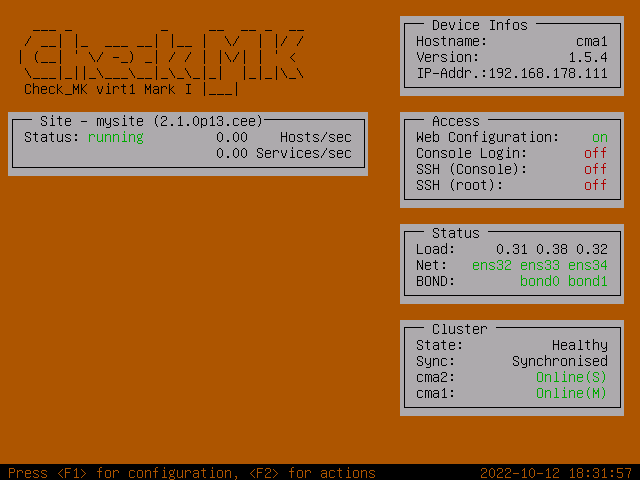
After the first synchronization has been completed, your cluster will be fully operational. You can view its status at any time on the cluster page.
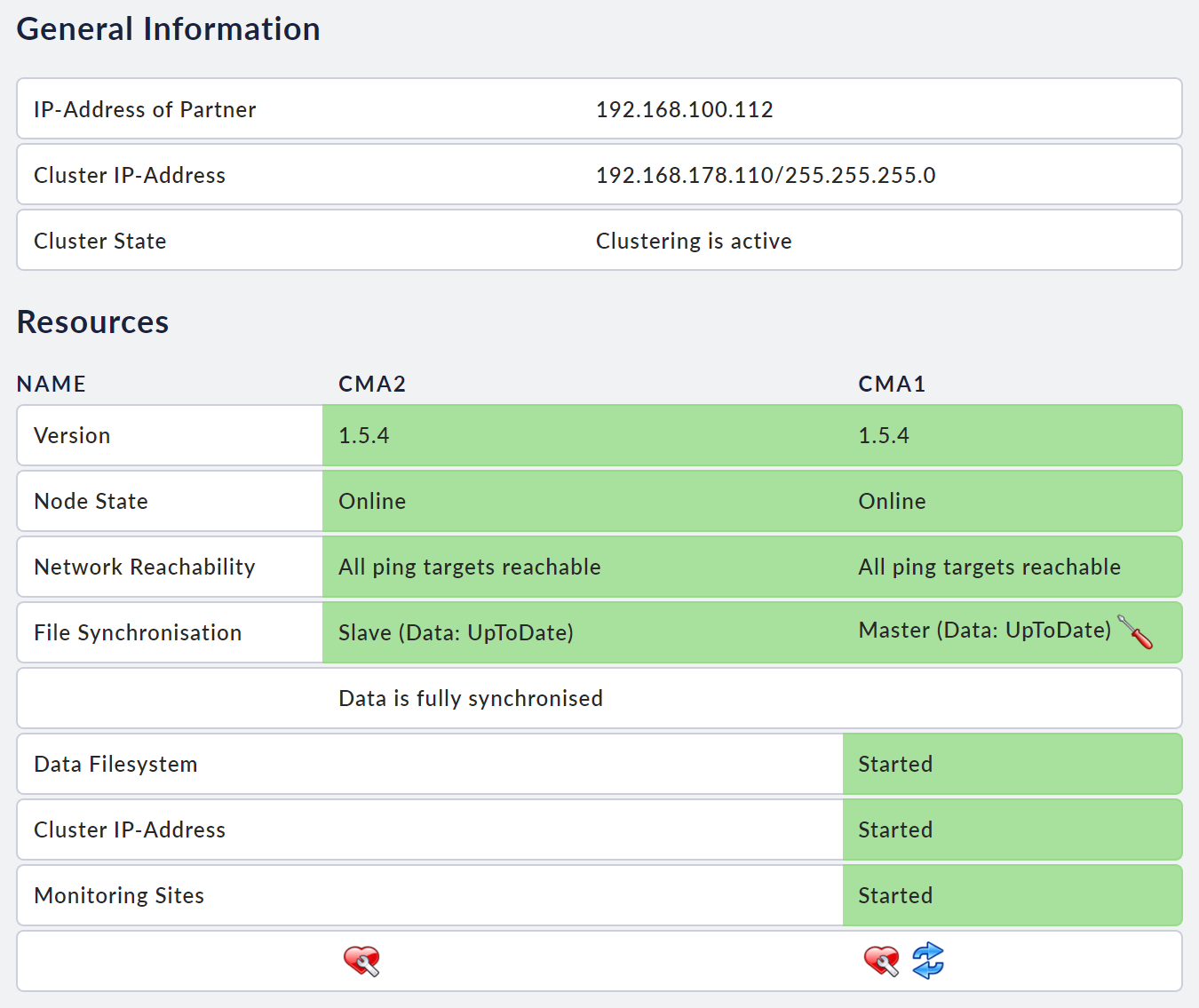
With the help of the console’s status view, you can also see the current state of the cluster in a summarized form in the Cluster box. The role for each respective node is displayed in brackets after the current status: for the active node M (for Main) and for the passive node S (for Subordinate).
5. Special features in the cluster
5.1. Access to resources
All requests to the monitoring sites, such as accesses to the web interface, as well as incoming messages such as SNMP traps or syslog messages to the Event Console or Livestatus requests, should normally always go via the cluster IP address.
You should need to directly access the individual nodes only under exceptional circumstances, such as during error diagnoses or updates of a specific node.
5.2. Device options
The settings, such as for time synchronization or name resolution, which were previously made independently on the individual units, are synchronized in the cluster between the two nodes.
However, you can only edit these settings on the respective active node. The settings are locked on the inactive node.
There are some device-specific settings, such as those for the Checkmk rack1 management interface, which you can edit at any time on the individual devices.
5.3. IP addresses or host names for the nodes
To be able to edit the IP configurations of the individual nodes, you must first disconnect the link between the nodes. To do this, click on Disconnect Cluster on the cluster page. You can then modify the settings as required via the web interfaces in the individual nodes.
After you have completed the modifications, you must then select Reconnect Cluster on the cluster page. If the nodes can reconnect successfully, the cluster will resume operation after a few minutes. You will be able to see the status on the cluster page.
5.4. Managing Checkmk versions and monitoring sites
The monitoring sites and Checkmk versions are also synchronized between the two nodes. You can only modify these in the active node’s web interface — both via its own and via the cluster IP address.
6. Administrative tasks
6.1. Updating from 1.4 to 1.5
In contrast to the firmware update within compatible versions described below, for example 1.5.1 to 1.5.2, you will need to proceed somewhat differently when updating 1.4 versions to the current 1.5 versions. The reason for this is that 1.5 is based on a new Debian version. In short, this means that you will have to take the cluster completely offline for a short time — you will therefore experience a downtime. With regular updates, it is sufficient to put the cluster’s individual nodes into a maintenance state in order to carry out the update. For this major update to 1.5, proceed as follows:
Disconnect the nodes from the cluster via Clustering > Disconnect Cluster.
Update the nodes one after the other as described in the appliance main article.
Reconnect the nodes to the cluster via Clustering > Reconnect Cluster.
Check whether your sites use compatible Checkmk versions and update any if necessary as described appliance main article.
6.2. Firmware update in the cluster
A device’s firmware version is not synchronized even in cluster operation. Firmware updates are therefore performed individually on each node. However, this has the advantage that one node can continue monitoring while the other node is being updated.
When updating to a compatible firmware version, you should always proceed as follows:
First open the Clustering module in the web interface of the node that is to be updated.
Now click on the 'heart' icon in this node’s column and confirm the security prompt that follows. This sets the node to maintenance state.
Nodes in maintenance state release all resources that are currently active on the node, and the other node will take them over.
While a node is in the maintenance state, the cluster is not fail-safe. If the active node is switched off, the inactive node, which is in the maintenance state, does not take over the resources. If you now also put the second node into the maintenance state, all resources will be shut down. These resources will only be reactivated when a node is brought out of the maintenance state. You must always remove the maintenance state manually.
If the cluster page shows the following, you will see that the node is in the maintenance state:
Now you can perform the firmware update on this node, in the same way as on non-clustered appliances.
After you have successfully performed the firmware update, open the cluster page again. Remove the maintenance status from the updated device. The device will then automatically reinsert itself into the cluster, making the cluster fully functional again.
We recommend running the same firmware version on both nodes. You should therefore repeat the same procedure for the other node.
6.3. Dissolving a cluster
It is possible to detach the nodes from a cluster and continue to operate them individually. In doing so, you can continue to use the synchronized configuration on both devices or, for example, reset one of the devices to the factory state and reconfigure it.
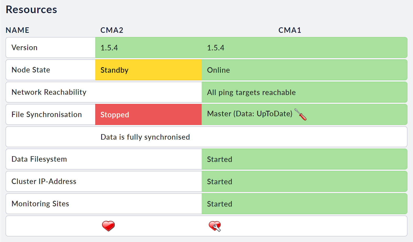
You can remove one or both nodes from the cluster during operation. If you want to continue using both nodes with the current data, you must first ensure that the synchronization of the data is working properly. You can see this on the cluster page.
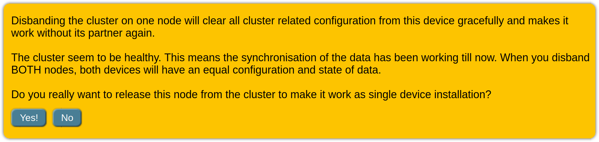
To dissolve a cluster, click Disband Cluster on the web interface’s cluster page. Note the text of the following security query. In all the possible situations, this will tell you what state the respective device will be in after the connection has been terminated.
The separation of the appliances must be carried out separately on both nodes so that both appliances can be operated individually in the future.
If you want to use only one of the devices in the future, detach the cluster on the device that you want to continue using and then restore the factory state on the other device.
After you have disconnected a node from the cluster, the monitoring sites are not restarted automatically. You must do this manually afterwards if necessary.
6.4. Replacing an appliance
If the hard drives in the old appliance are in working order, you can remove them from the old appliance and install them in the new appliance and wire the new appliance exactly as the old appliance was wired — and then switch it on. After start-up, the new unit will reinsert itself into the cluster in the same way as the old unit.
If you want to completely replace an old appliance with a new one, you should proceed in the same way as if you were completely dissolving the cluster. To do this, select one of the existing devices, remove it from the cluster and create a new cluster with this and the new device.
7. Fault diagnosis
7.1. Logging
Cluster management is largely automatic. Automatic processes on the nodes decide which resources are to be started and stopped on each device. This behavior is logged in detail in the form of log entries. You can access these entries from the cluster page via the Cluster Log button.
Note, that these entries, just like the other system messages, are lost when the unit is restarted. If you want to receive the messages beyond that, you can download the current log file via your browser or permanently set up a forwarding of the log messages to a syslog server.